Skene Lights Installation on the BMW CE-04

triangletom

Active member
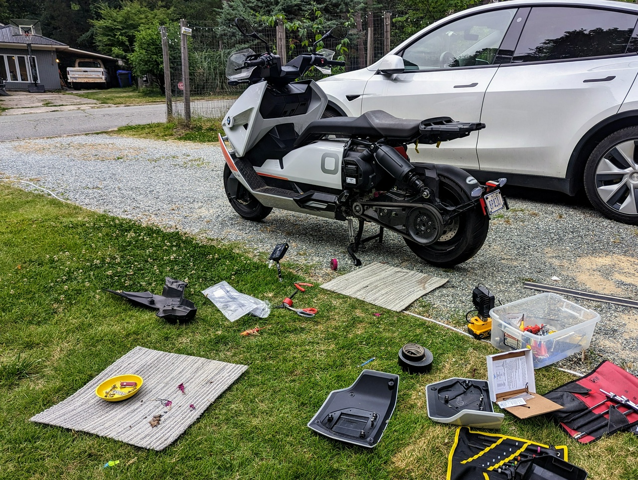
Before allowing my kids to ride on the back of my BMW CE 04, I wanted to drastically improve its visibility. It turns out that there is a company that specializes in doing just that: skenelights.com

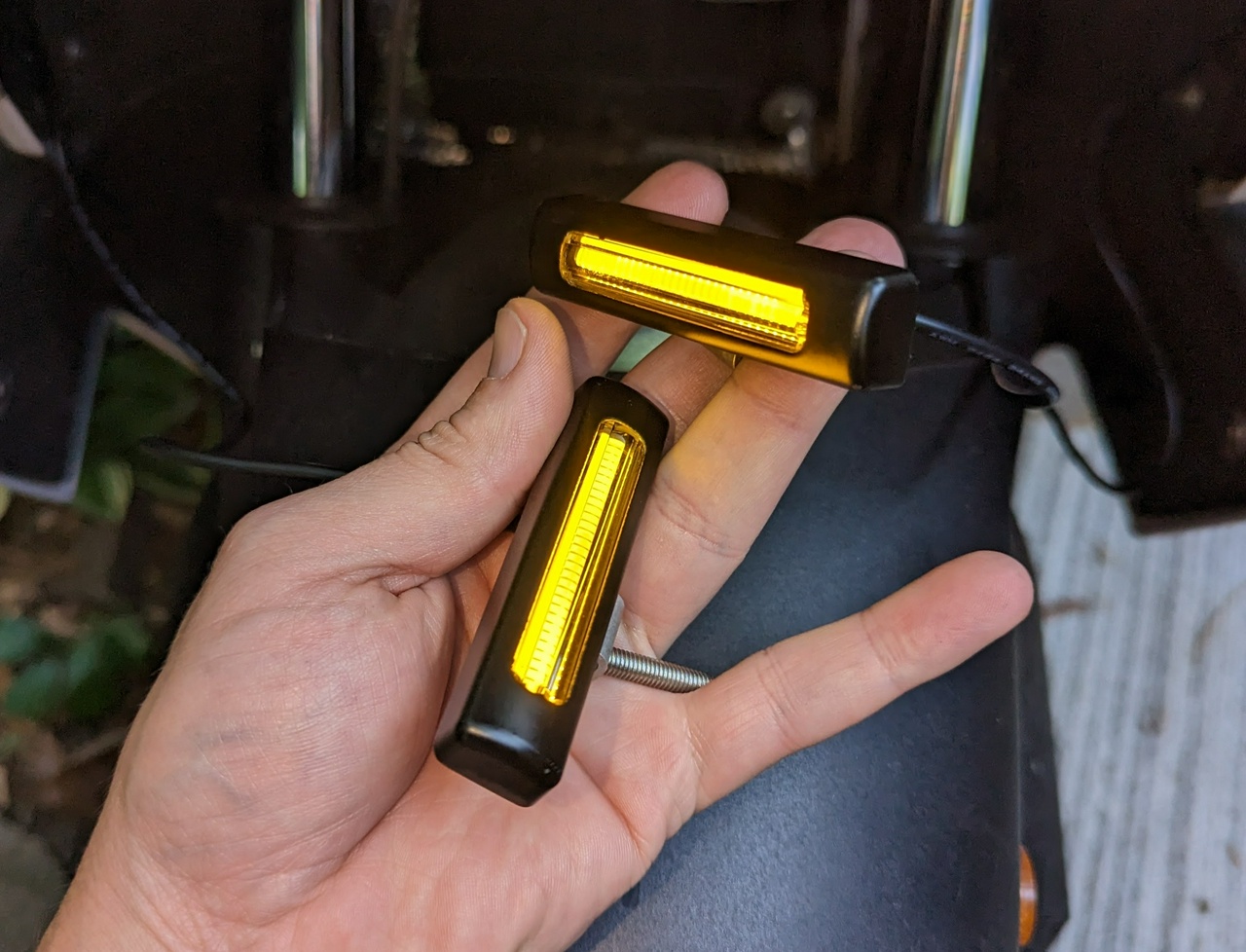
The lights they sell have a unique conspicuity filter, which uses the motion-detecting characteristics of human vision to enhance visibility. It's difficult to accurately capture the appearance with a cell phone camera due to the rolling shutter, but this is what it looks like before sunset and at night:


These lights can also work as an extra set of blinkers, and in the case of the rear lights, they will also light up if I hit the brakes or through deceleration if I even just let off the throttle.
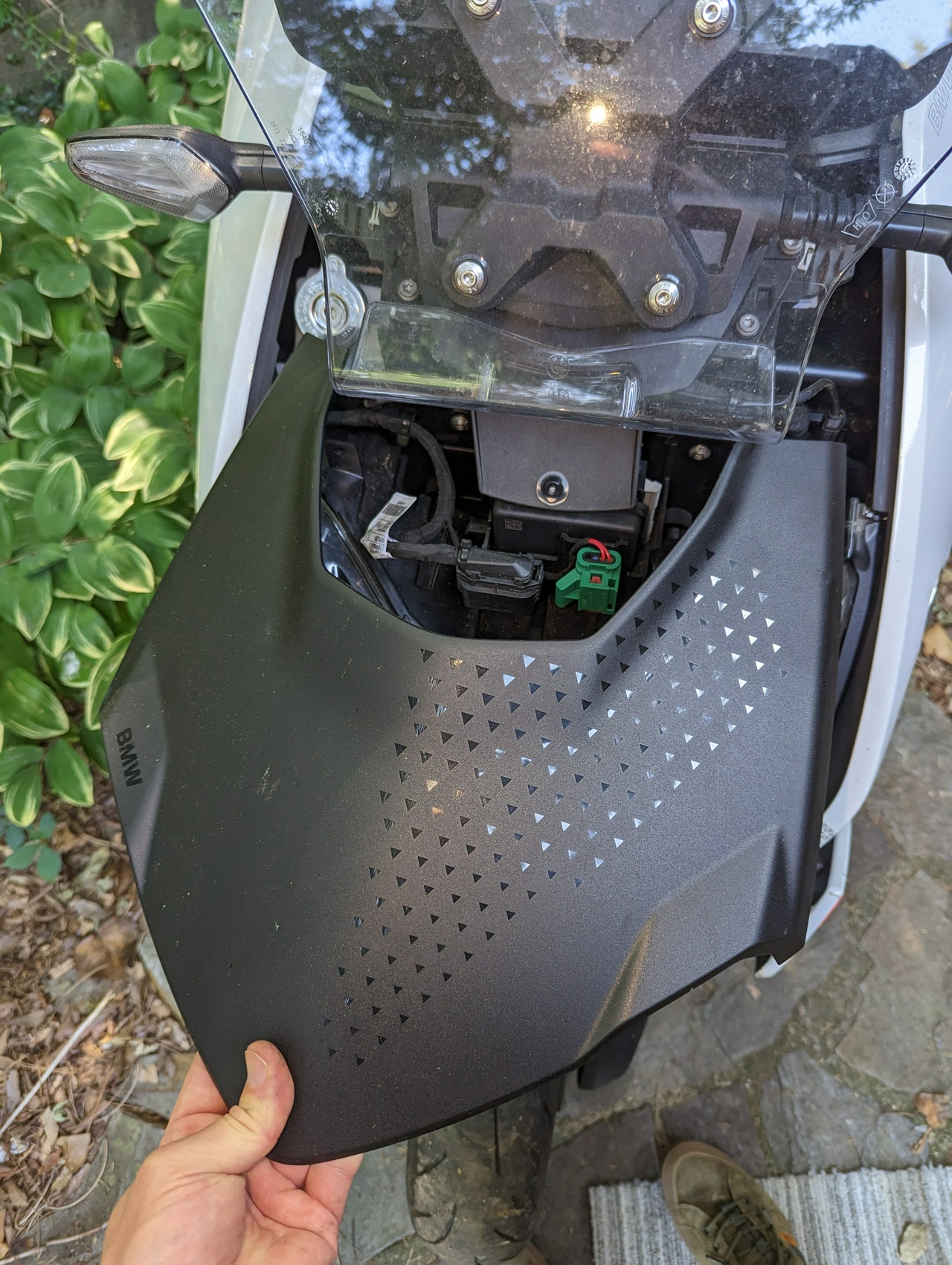
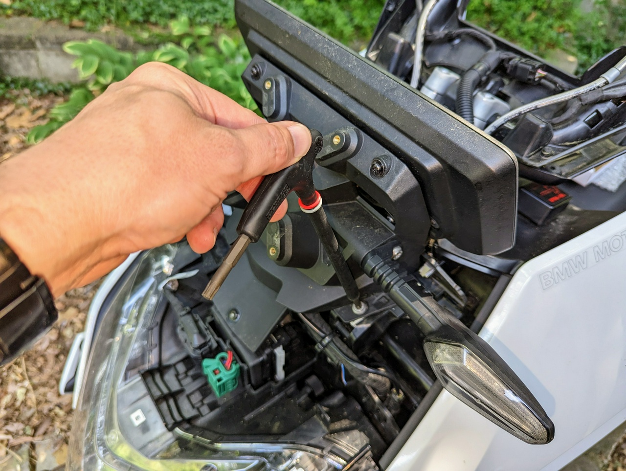
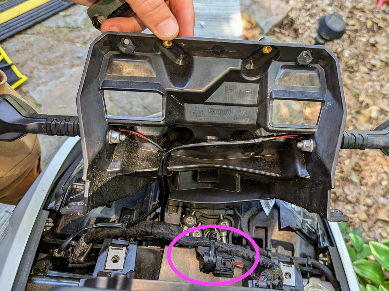
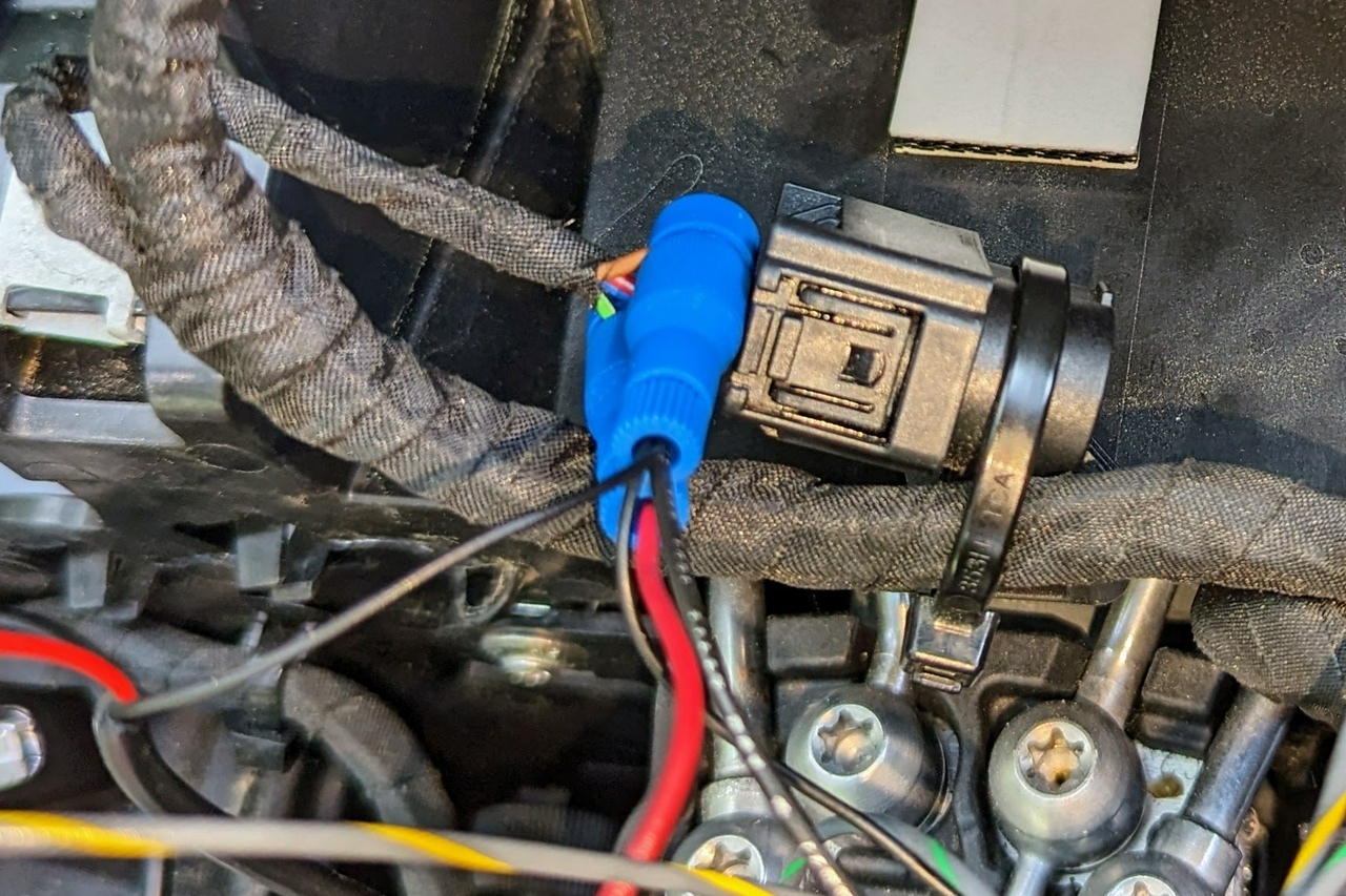
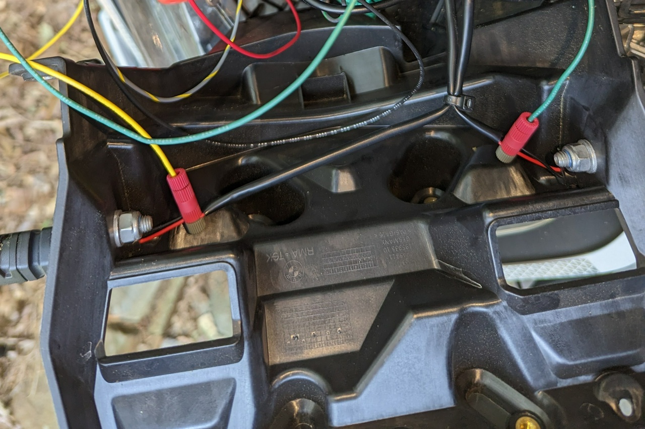
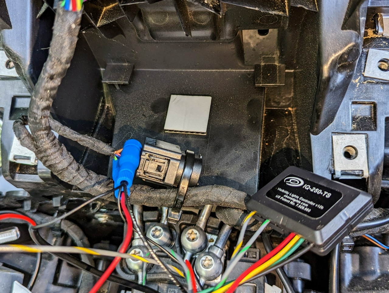
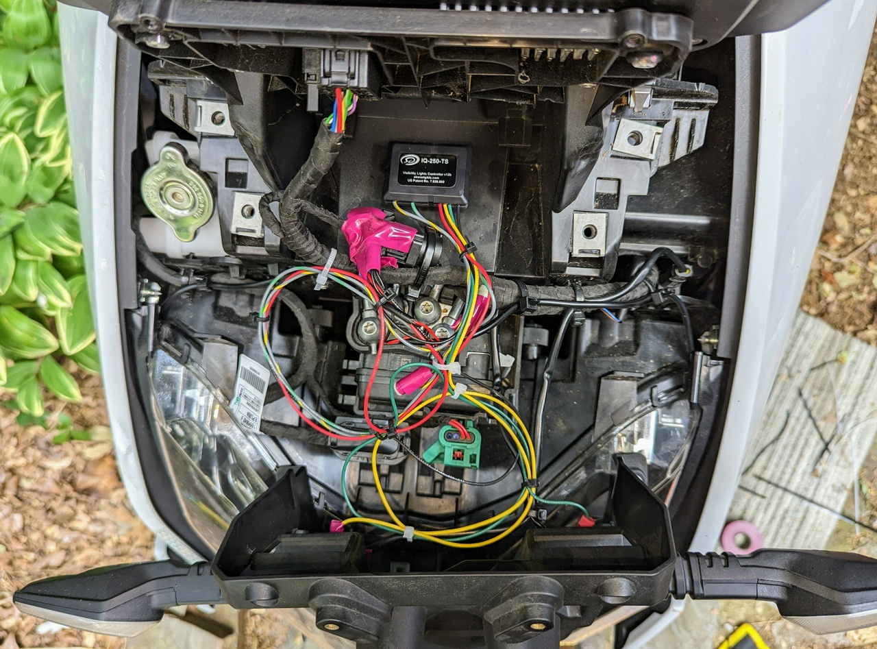
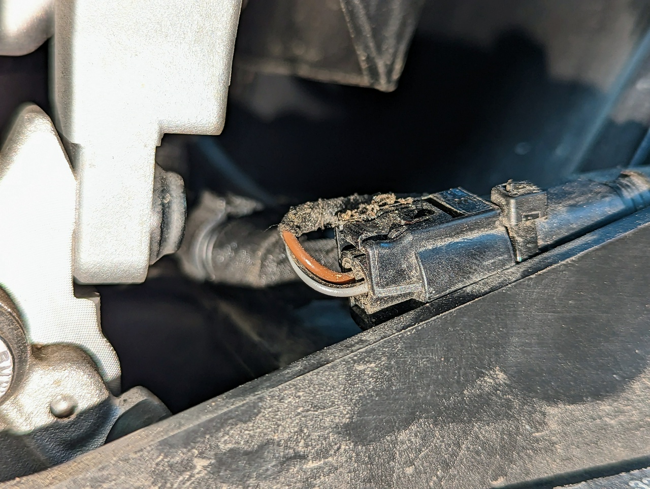
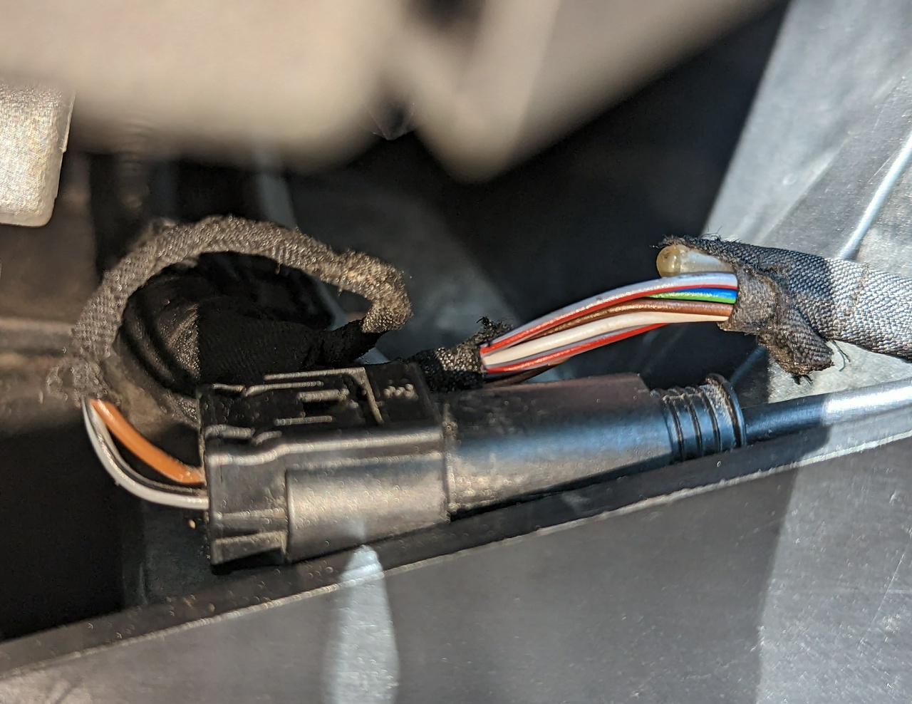
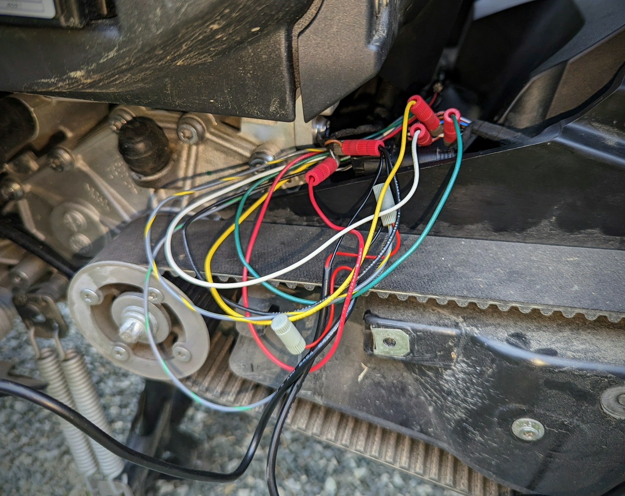
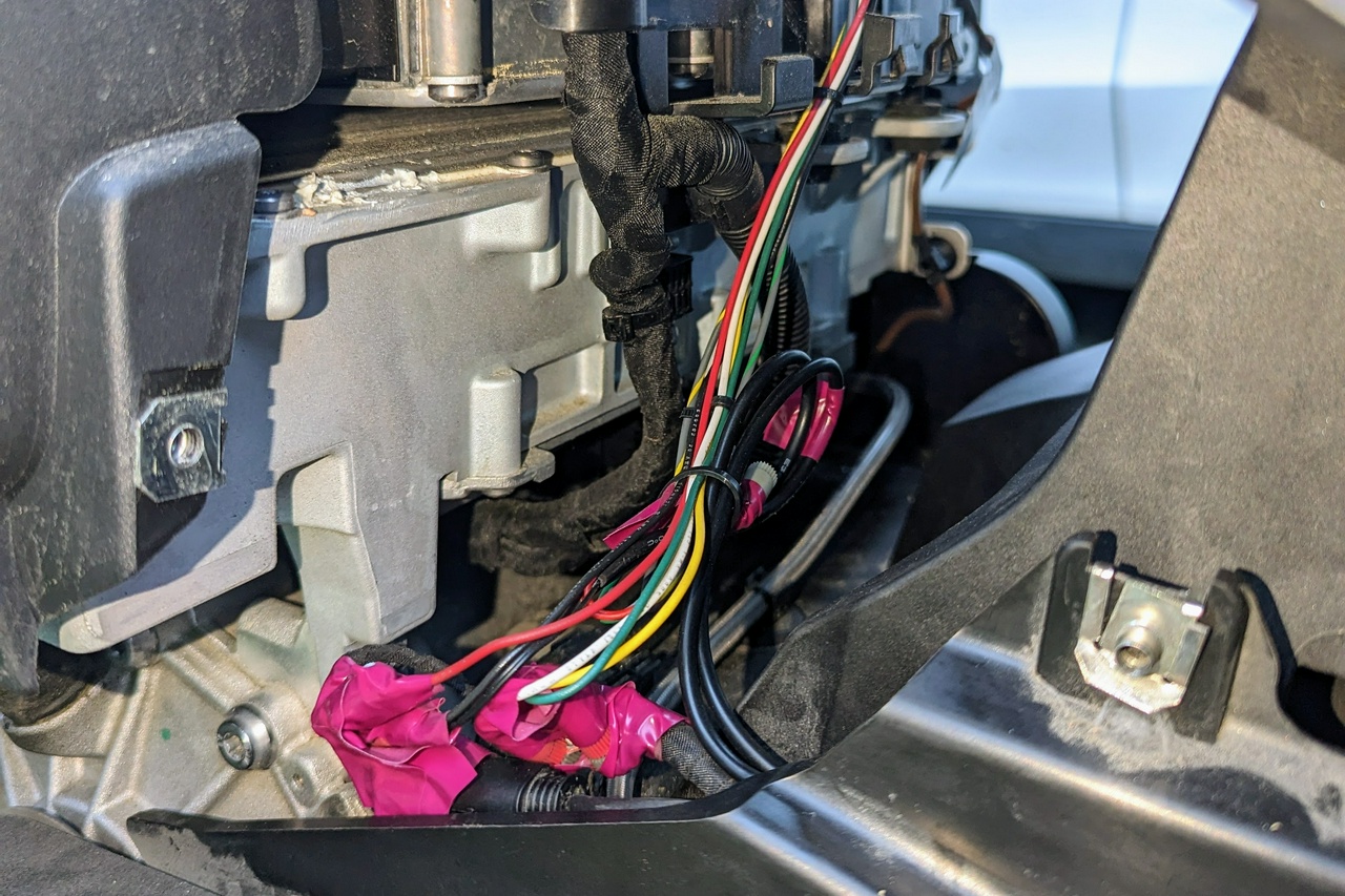
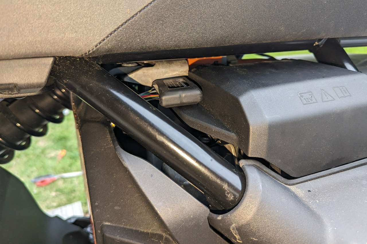
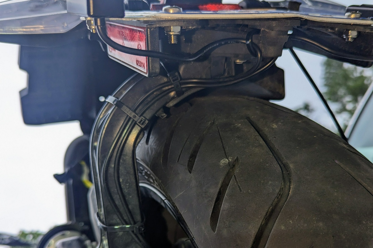
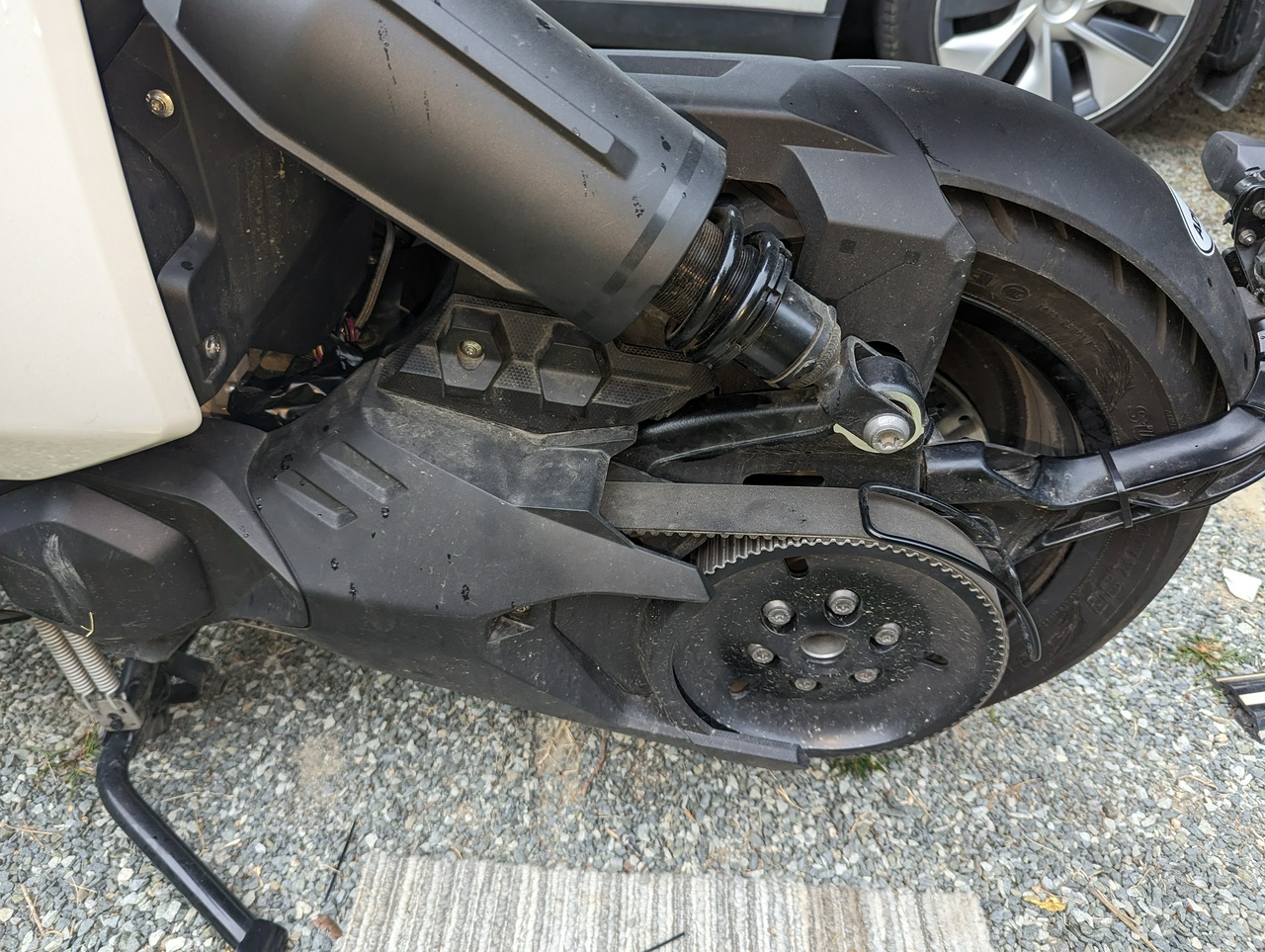
The biggest problem with installing 3rd party lights is knowing how and where to plug them in. As BMW has chosen not to publish an electrical diagram, it took me a full day to figure it out. This was my first time using Posi-Tap connectors, which was easier than I thought: after watching a Posi-Tap install video, I only had one wire that required multiple taps: the 12V+ lead on the license plate light.

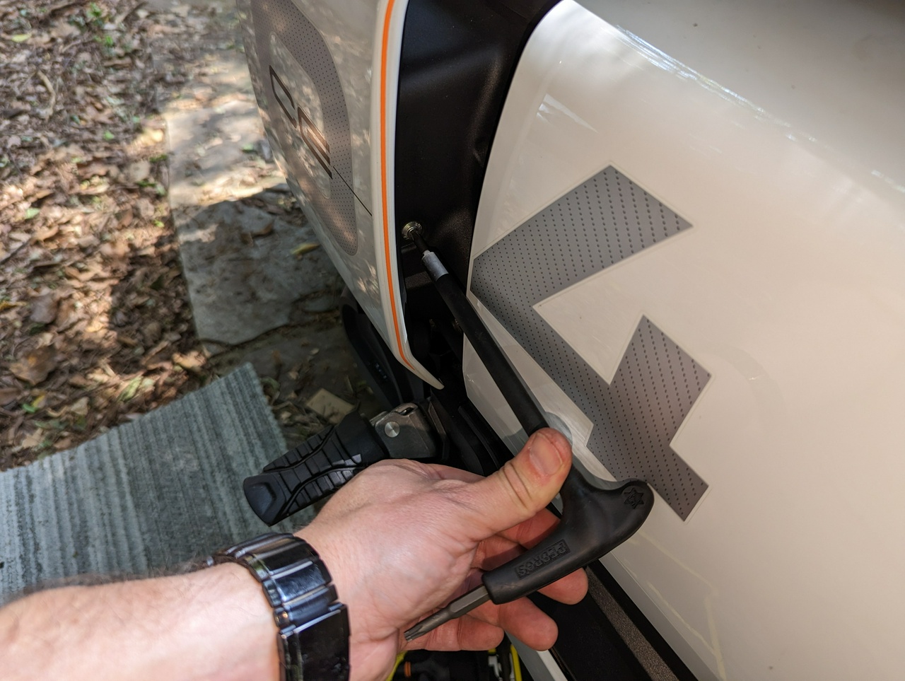
This guide is meant to capitalize on my misery and for your use as a time-saving CE-04-specific supplement to the official Skene installation guides. Now, let’s go take things apart!

ucmfIMdD.jpg
 

triangletom

Active member

Photon Blaster-TS Front Lights Installation​

  • Time: 2 hours if this is your first time installing lights
  • Tools: T30 wrench, T25 wrench
  • My wiring suggestion:
    • Switched +12V –> Green alarm wire
    • Ground –> Brown alarm wire
    • Left Turn Signal –> Red left turn signal wire
    • Right Turn Signal –> Red right turn signal wire

1. Remove the front panel​

The front panel on the CE-04 slides down – no tools required.

7hYeyHHs.jpg


Underneath this panel are the headlight adjusters, an emergency T25 wrench, and an ODB-II port.

2. Remove the windscreen.​

This is held by 4 T25 screws. If you have the high windscreen, you may have more screws than this, but you only need to remove the bottom 4 for this project.

3. Remove the relay and indicator panel​

There are 4 T30 screws underneath the windscreen and behind the display.

JT537emH.jpg


Once unscrewed, you can access all the wires you need to install auxiliary lights for the BMW CE 04. First, we are going to use the alarm for 12V switched power and ground – highlighted below:

rEZK5Kxj.jpg


4. Tap the alarm connector​

I don't have an alarm, so my scooter came with this 120-ohm resistor (BMW part 7668405 01) installed. Either way, the idea is the same: install the larger blue Posi-Tap's on the brown (ground) and green (12V switched power) wires.

rRDvVdux.jpg


Once you've done that, connect the wires up to your Photon Blasters and power up the CE 04 to confirm basic operations:

2v8k8JR6.jpg


If your taps were successful, the lights should now work when you turn your scooter on. If not, check that you successfully pierced the cable, as it is easy to miss the center of the plug you are tapping into – DAMHIK.

5. Tap the turn signals​

If you have the turn-signal variety of the Photon Blasters (-TS suffix), tap into the red wires on the turn signal cables too. Thankfully they are straightforward to access:

eP43KGBJ.jpg


6. Secure the controller​

Try your turn signals, and if they work, you can move on to placing the velcro for the controller on the flat area between the alarm and the screen:

N04Wc3lh.jpg


7. Route the LED cables​

Before you clean up your cable mess, I suggest screwing the Skene lights into their eventual home at the bottom of the wheels. You can drape them across the front of the fairing on either side. I experimented with several ideas, such as removing the panels and using the gaps between them, but in the end, I went with a simple approach (no additional unscrewing required):

SE963ky0.jpg


The installation guide suggests a drip loop so water does not drip down the cable and into the lights.

N96XQQ0V.jpg


I found that introducing this bend into the cable revealed wires on the right side light, so I added some reinforcement electrical tape to protect it:

n1kKL9fj.jpg


I routed the cable up the fork protector and added a zip tie to the fork boots to make sure that the cable didn't pop out from behind the protector:

k2H9Zz5t.jpg


Now get the bike on the center stand, and push the wheel full lock in either direction to ensure that the wires are not run so tightly that they interfere with steering.

NSxFDObr.jpg


8. Clean up​

Then go ahead and wrap all of your connectors with electrical tape and use every twist tie you can to make things look nice. Here is what things looked like under the hood for me before I put the panels back on:

qhqYV6JO.jpg


I was able to hide all of the wires beneath the turn signal panel so that you couldn't even tell that evil things had been done below:

FqBiZ46x.jpg


Now slide the front panel back into place, put the screen on, and level out the LEDs. If your lights aren't pulsing, you may need to enable the conspicuity mode – see the manual for programming notes.
 

triangletom

Active member

P3 Rear Lights (IQ-260 Series) Installation​

  • Time: 2 hours
  • Tools: T25 wrench, multi-tool, scissors
  • Suggested wiring:
    • Switched +12V –> white/grey wire to the license plate light
    • Ground –> brown wire to the license plate light
    • Left Turn Signal –> white wire to the indicator cluster
    • Right Turn Signal –> blue/green wire to the indicator cluster
    • Brake – one of the two lavender/red wires to the indicator cluster
On the CE-04, the rear lights are more challenging to install than the front lights. Having removed the rear wheel before to replace a broken indicator light, I opted to write up installation instructions that do not require wheel removal – even if doing so does provide a slightly cleaner install.

1. Remove panels​

First, remove the 3 T25 bolts holding the belt cover. The arrow points to where we will be tapping the wires:

XIqfSeOt.jpg


Remove the white panels on both sides for more room – both have one T25 bolt to remove before you can pull them out.

luEZFie5.jpg


2. Tap the power leads​

You will need to strip the fabric from two cables: the 2-wire license plate light cable with a quick connector and a 6-wire indicator cluster cable. I suggest carefully removing the license plate light cable using the quick connector and a small flat-head screwdriver for easier access.

atm4pXNX.jpg


If you end up breaking the safety latch on it, no big deal – I broke mine on the second go around. Once detected, install PosiTaps on these two wires for the ground (brown) and 12V switched power (silver/black).

Once you do this, perform a power-on test of the lights.

3. Tap the signal leads​

The 6-wire indicator cluster cable is behind the license plate light and is slightly more difficult to unwrap. I used a small pocket knife and pair of scissors to cut into the section where the thick translucent plastic protector part ends, careful not to cut into the wires:

NScDC402.jpg


You'll need to install Posi-Taps onto the white wire (left turn signal), blue/green wire (right turn signal), and one of the lavender/red wires (brake). The result looks somewhat like a rainbow snake exploded:

trQeMOuO.jpg


4. Wrap the taps​

I wrapped the cables up in electrical tape (I regret using purple), and then removed the back panel (T25 screws) to cleverly hide the tapped cables and route the controller to its final resting space above the 12V battery.

hfi5eK6M.jpg


5. Secure the controller​

I could have hidden the controller below, but since I had the decelerometer version, I needed a level surface, so I chose the space just above the 12V battery.

bxOyzqIY.jpg


As the manual suggested, I installed a zip tie to the cables, and then I used some duct tape to keep it from rattling around.

6. Route the LED cables​

Once I knew how long I needed the wires to run, I installed the rear lights, running the wires beneath the swing arm until they could join the standard indicator wires. If you remove the rear wheel, you can instead access the small channel underneath the plastic:

Cw1UQhrn.jpg


Once you put humpty dumpty back together again, it will look something like this:

MiJEmDhk.jpg


While I don’t love the visible tie wraps on the mudguard holder, I also don’t love removing and reinstalling the rear wheel.

I suspect I could have likely gotten a cleaner install by tapping closer to the fuse blocks, but I was trying to stay out of the high-voltage area of the bike.


In Closing​

The Skene lights were a pain to install but well worth the added visibility. If I was to criticize anything, it'd be the wire boot on the Photon Blaster LED lights and the fact that when the turn signal is on, both the Photon Blasters will display an alternate flashing pattern.
 

wspollack

Active member
@triangletom:

Superb write-up, very beneficial to the CE-04 community.

In my first year of C 400 GT ownership, I put Skene P3-TS out back and Skene Photon Boosters up front. Very bright lights. (I describe the work on that scoot in a somewhat similar manner to your work in my gallery https://billanddot.com/C400GT/ .)
 

mzflorida

Active member
I add the photon blasters to all of my bikes. After installing them drivers pulling out in front of me from either the left or right were virtually eliminated. No way to definitively say that the photon blasters contributed to this but pretty good anecdotal evidence. Others claim the same. Anyhow, great write up and great choice on the Skene.
 
Top
AdBlock Detected

We get it, advertisements are annoying!

Sure, ad-blocking software does a great job at blocking ads, but it also blocks useful features of our website. For the best site experience please disable your AdBlocker.

I've Disabled AdBlock
No Thanks